Betatron particle accelerator | Uses Applications and Diagram
A betatron is a device used for accelerating electrons (also known as beta particles) to high speeds using induced electric fields produced by changing magnetic fields.
Such high energy-electrons can be used for basic research in physics as well as for producing x-rays for applied research in industry and for medical purposes such as cancer therapy. The betatron provides an excellent illustration of the ‘’ reality ’’ of induced electric fields.
Principle:
Its principle is based on electromagnetic induction. The varying electric field gives rise to an induced electric field on an electron moving in a circular orbit. Due to this induced field electrons were accelerated.
Typically, betatrons can produce energies of 100 MeV, in which case the electrons are highly relativistic (v= 0.99987c). betatrons can produce enormous currents, in the range of 103 to 105 A.
They are, however, pulsed machines, producing pulses of typical width or less separated by time intervals in the range of 0.01 – 1s.
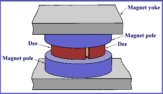
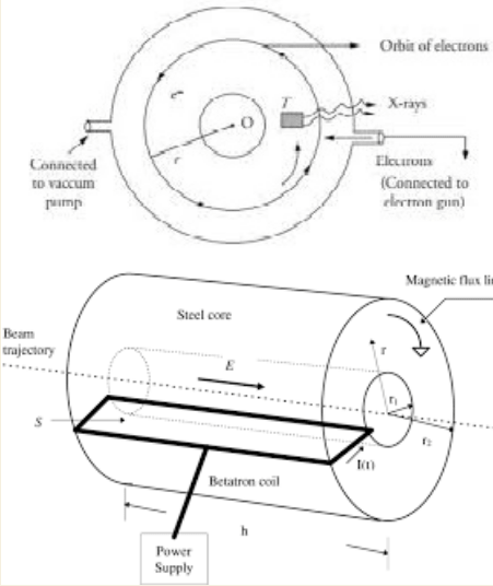
The figure shows a cross-section through the inner structure of a betatron. It consists of a large electromagnetic M. The field of which ( indicated by the field lines) can be varied by changing the current in coils C.
The electrons circulate in the evacuated ceramic doughnut-shaped tube marked D. Their orbit is at right angles to the plane of the figure, emerging from the left and entering at the right.
The magnetic field has several functions:
- It guides the electrons in a circular path;
- the changing magnetic field produces an induced electric field that accelerates the electrons in their path;
- it introduces electrons into the orbit and then removes them from the orbit after they have attained their full energy; and
- it provides a restoring force that tends to resist any tendency of the electrons to leave their orbit, either vertically or radially. It is remarkable that the magnetic field is capable of performing all these operations.
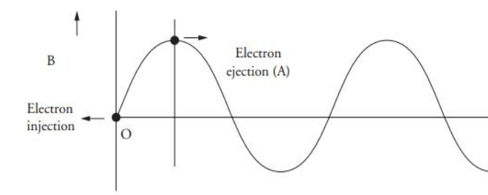
- The coils carry an alternating current and produce a magnetic field. for electrons to circulate in the directions as shown in fig. (counterclockwise as viewed from above), the magnetic field must be pointing upward (taken as positive). Furthermore, the changing field must have a positive slope (dB/dl > 0 so that dØB /dt > 0 ) if the electrons are to be accelerated ( rather than decelerated) during the cycle. Thus only the first quarter-cycle of the fig is useful for the operation of the betatron; the electrons are injected at t = 0 and extracted at t = T/4. For the remaining three-quarters of a cycle, the device produces no beam.
Construction of Betatron:
It consists of a ring-shaped vacuum tube chamber placed between the poles of an electromagnet. By applying suitable electric and magnetic fields electrons emitted from an electron gun are forced to move in a circular path. A high-voltage AC supply is needed.
Betatron Working:
The electrons are injected in during the first quarter of the cycle in which the magnetic field is increasing. The magnetic field is perpendicular to the electron which causes the electron to move in a circular path.
Drawback:
- The size of the electromagnet is very large (almost 130 tones).
- A very large amount of power is needed.
- The ejection process of electrons is complex.
Limitations of Betatron:
Betatron works over 300 MeV beyond this limit, electrons loss radiations and the net gain in maximum energy becomes negligible